Table of Contents
ToggleIn transportation engineering, curves are essential elements that form the backbone of railway and highway alignments. A curve represents a continuous and regular change in direction of the route, allowing for smooth transitions between straight sections.
Curves serve multiple purposes in transportation design:
- They enable routes to navigate around obstacles and conform to the natural terrain.
- They facilitate gradual changes in direction, enhancing safety and comfort for travelers.
- They help optimize route efficiency by allowing more direct paths between destinations.
The geometry of a curve is carefully calculated and designed to ensure it meets specific engineering criteria. These criteria take into account factors such as vehicle dynamics, passenger comfort, safety standards, and the physical limitations of the terrain.
In railway and highway design, curves are always tangential to the straight sections they connect at both ends. This tangential property is crucial as it ensures a smooth transition from straight to curved sections and vice versa, minimizing sudden changes in direction that could compromise safety or comfort.
Types of Curve
curves are broadly categorized into two main types: horizontal curves and vertical curves. Each type serves a distinct purpose in alignment design and contributes to the overall functionality and safety of the route.
i. Horizontal Curve
Horizontal curves change the alignment direction in the horizontal plane. They are essential for navigating around obstacles, conforming to topographical features, and creating efficient routes. Key aspects of horizontal curves include:
- Circular Curves: The most common type, with a constant radius throughout.
- Spiral Curves: Also known as transition curves, these provide a gradual change in curvature between straight sections and circular curves.
- Compound Curves: Consist of two or more simple curves of different radii, turning in the same direction.
- Reverse Curves: Two curves turning in opposite directions, connected by a common tangent.
1. Simple Circular Curve
A simple circular curve, often referred to simply as a circular curve, is a fundamental element in horizontal alignment design for railways and highways. It is characterized by the following key features:
- Geometry: The curve consists of a single arc segment of a circle. This means it maintains a constant radius throughout its length.
- Tangentiality: The curve is tangential to both straight sections it connects. In the given example, it’s tangent to the straight sections AT1 and CT2. This tangential property ensures a smooth transition between straight and curved sections.
- Single Radius: Unlike compound or spiral curves, a simple circular curve has only one radius that remains constant from the beginning to the end of the curve.
- Point of Curvature (PC) and Point of Tangency (PT): The points where the curve begins and ends, transitioning from and to straight sections, are called the Point of Curvature and Point of Tangency respectively.
- Deflection Angle: The angle between the two tangents (straight sections) is an important parameter in designing the curve.
- Curve Length: The length of the arc between the PC and PT is determined by the radius and the deflection angle.
Simple circular curves are widely used in transportation engineering due to their simplicity in design and construction. However, they have limitations, particularly at higher speeds, where spiral transition curves may be necessary to provide a more gradual change in lateral acceleration.

2. Compound Curve
A compound curve is a more complex horizontal alignment element used in railway and highway design. It has several distinctive characteristics:
- Multiple Arcs: A compound curve consists of two or more circular arcs connected in sequence. Each arc has a different radius, allowing for more flexibility in alignment design.
- Same Direction: All arcs in a compound curve bend in the same direction. This maintains a consistent turning direction throughout the curve.
- Different Radii: Each arc segment has its own unique radius. This allows engineers to design curves that can better adapt to varying terrain or right-of-way constraints.
- Common Side: The centers of all the circular arcs lie on the same side of the common tangent. This ensures a smooth transition between the different arc segments.
- Common Tangent Points: The point where two arcs meet is tangential to both arcs, ensuring a smooth transition between segments.
- Flexibility: Compound curves offer more flexibility in design compared to simple circular curves, allowing alignments to better conform to topographical features or avoid obstacles.
- Transition Points: The points where one arc transitions to another are critical in compound curve design and are carefully calculated to ensure smooth vehicle operation.
- Applications: Compound curves are particularly useful in mountainous terrain, urban areas with space constraints, or when connecting to existing infrastructure with specific geometric requirements.
While compound curves offer greater design flexibility, they also require more complex calculations and careful consideration of vehicle dynamics to ensure safe and comfortable operation.

3. Reverse Curve
A reverse curve is a specialized type of horizontal alignment element used in railway and highway design. It has several distinctive features:
- Composition: A reverse curve consists of two circular arcs connected in sequence.
- Opposite Directions: The key characteristic of a reverse curve is that the two arcs turn in opposite directions. This allows for a change in the overall direction of the alignment.
- Radii: The two arcs may have the same radius or different radii, providing flexibility in design.
- Center Positions: The centers of the two circular arcs are located on opposite sides of the curve. This is what allows for the reversal in direction.
- Common Tangent Point: At the junction where the two arcs meet, there is a common tangent point. This ensures a smooth transition between the two opposing curves.
- S-Shape: Due to the opposing directions of the arcs, reverse curves often form an S-shape when viewed from above.
- Applications: Reverse curves are particularly useful in situations where the alignment needs to navigate around obstacles, conform to property boundaries, or make significant directional changes in limited space.
- Design Considerations:
- The transition between the two arcs requires careful design to ensure vehicle stability.
- Adequate sight distance must be maintained throughout the curve.
- Super-elevation (banking) transitions need special attention due to the reversal of direction.
- Limitations: Reverse curves can be challenging for vehicle dynamics, especially for longer vehicles or high-speed routes. They are generally avoided on high-speed alignments when possible.
- Variations: In some cases, a short tangent section might be introduced between the two arcs, forming what’s sometimes called a broken-back curve.
Reverse curves offer a solution for complex alignment needs but require careful engineering to ensure safe and comfortable operation for all types of vehicles using the route.

4.Transition Curve
A transition curve, also known as a spiral curve or easement curve, is a crucial element in modern railway and highway alignment design. It has several important characteristics and functions:
- Definition: A transition curve is a curve with a gradually changing radius, typically inserted between a straight section (tangent) and a circular curve, or between two circular curves of different radii.
- Purpose: The primary purpose of a transition curve is to provide a smooth, gradual change in lateral acceleration as a vehicle enters or exits a circular curve. This enhances safety, comfort, and stability.
- Varying Radius: Unlike circular curves, the radius of a transition curve changes continuously along its length. It usually starts with an infinite radius (straight line) and gradually decreases to match the radius of the connecting circular curve.
- Common Types of Transition Curve:
i. Clothoid spiral (or Euler spiral): The most commonly used transition curve
ii. Cubic parabola
iii. Lemniscate curve - Key Benefits:
i. Reduces the sudden lateral force experienced by vehicles entering or exiting a curve
ii. Allows for a gradual application of superelevation (banking of the road or track)
iii. Improves sight distances on curves
iv. Enhances the aesthetic appearance of the alignment - Design Parameters:
Length of the transition curve
Initial and final radii
Design speed
Rate of change of lateral acceleration - Applications:
High-speed railways
Modern highways and freeways
Roller coasters and other amusement rides - Considerations:
Longer transition curves are generally more comfortable but require more space
The design must balance comfort, safety, construction cost, and land use - Mathematical Representation: The curvature of a transition curve typically changes linearly with its length, which can be represented mathematically for precise design and layout.
Transition curves are essential elements in modern transportation infrastructure, particularly for routes designed for higher speeds. They significantly contribute to the safety and comfort of passengers and drivers by providing a smooth entry and exit from circular curves.

ii. Vertical Curves
Vertical curves are used in the design of the longitudinal profile of roads and railways to provide a smooth transition between different gradients. There are two main types of vertical curves:
1. Crest Curves
Crest curves are a critical component of vertical alignment in road and railway design, occurring at the top of hills or where the gradient transitions from positive to negative. Here’s a more in-depth look at crest curves:

- Geometry and Design
- Shape: Typically designed as a parabolic curve due to its simplicity and effectiveness
- Symmetry: Usually symmetrical about the vertex (highest point)
- Length: Determined by the difference in grades and design speed
- K-value: Represents the horizontal distance required for a 1% change in grade
- Primary Design Considerations
- Sight Distance: The most critical factor in crest curve design
- Stopping Sight Distance (SSD): Ensures drivers can see far enough ahead to stop safely
- Passing Sight Distance (PSD): Important on two-lane roads for safe overtaking
- Comfort: Minimizing the rate of vertical acceleration/deceleration
- Drainage: Ensuring water doesn’t pool at the curve’s highest point
- Sight Distance: The most critical factor in crest curve design
- Mathematical Representation
- The general equation of a parabola is used: y = ax^2 + bx + c
- The rate of change of grade is constant along the curve
- Types of Crest Curves
- Short Curves: Where the curve length is shorter than the sight distance
- Long Curves: Where the curve length exceeds the sight distance
- Design Speed Implications
- Higher design speeds require longer, flatter crest curves
- This ensures adequate sight distance at higher velocities
- Safety Considerations
- Potential for hidden hazards just beyond the crest
- Risk of vehicles becoming airborne if curve is too sharp
- Aesthetic Considerations
- Crest curves contribute to the road’s overall appearance and how it fits into the landscape
- Longer, flatter curves generally provide a more pleasing appearance
- Construction and Maintenance
- Proper compaction is crucial to prevent settlement at the crest
- Drainage systems must be carefully designed and maintained
- Environmental Impact
- Crest curve design can affect the amount of earthwork required, influencing the project’s environmental footprint
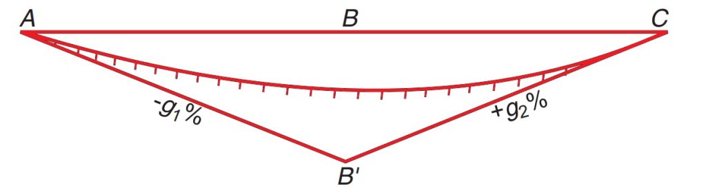
2. Sag Curves
Sag curves are essential elements in vertical alignment design, occurring in valleys or where the gradient changes from negative to positive. Here’s a comprehensive look at sag curves:
- Geometry and Design
- Shape: Typically designed as a parabolic curve, similar to crest curves
- Symmetry: Usually symmetrical about the low point
- Length: Determined by the change in grade, design speed, and comfort criteria
- K-value: Represents the horizontal distance needed for a 1% change in grade
- Primary Design Considerations
- Driver Comfort: More critical than in crest curves due to gravitational effects
- Headlight Sight Distance: Crucial for nighttime driving safety
- Drainage: Preventing water accumulation at the low point
- Mathematical Representation
- Uses the general equation of a parabola: y = ax^2 + bx + c
- The rate of change of grade is constant along the curve
- Types of Sag Curves
- Visible sag curves: Where the entire curve is visible to the driver
- Hidden sag curves: Where part of the curve is hidden from the driver’s view
- Design Speed Implications
- Higher speeds require longer, flatter sag curves for comfort
- Nighttime visibility becomes more critical at higher speeds
- Safety Considerations
- Potential for hydroplaning if drainage is inadequate
- Risk of increased stopping distances on wet pavements
- Aesthetic Considerations
- Sag curves can enhance the visual flow of the road
- They can be designed to complement the natural terrain
- Construction and Maintenance
- Proper subgrade preparation is crucial to prevent settling
- Drainage systems require regular maintenance to prevent clogging
- Special Applications
- Underpasses and tunnels often incorporate sag curves
- In urban areas, sag curves may need to accommodate underground utilities
- Headlight Illumination
- Critical in sag curve design, especially for nighttime driving
- The curve should allow headlights to illuminate the road surface adequately
- Comfort Criteria
- Based on the rate of vertical acceleration/deceleration
- More stringent than for crest curves due to the combined effect of gravity and centrifugal force
- Coordination with Horizontal Alignment
- Avoid placing sag curves near sharp horizontal curves to prevent disorientation
- Drainage Considerations
- Adequate longitudinal and cross slope for efficient water removal
- May require special drainage structures at the low point
- Environmental Impact
- Can affect the amount of cut and fill required
- Proper design can minimize erosion and sediment transport