

Turbine Flow Analysis and Gradient Lines
Problem Statement
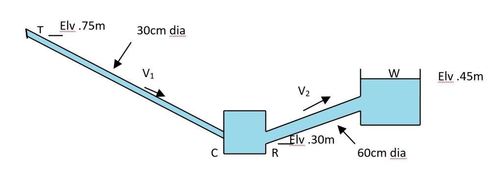
The head extracted by turbine CR in the figure is 60m and the pressure at T is 505 KN/m². For losses of 2V²₂/2g between W and R and 3V²₁/2g between C and T, determine:
(a) how much water is flowing, and
(b) the pressure head at R.
Draw the energy gradient line and hydraulic gradient line.
Given Data
| Diameter of pipe TC (d₁) | 30 cm = 0.3 m |
| Diameter of pipe RW (d₂) | 60 cm = 0.6 m |
| Pressure at T (PT) | 505 kN/m² = 505 kPa |
| Head loss between C and T | hLTC = 3V²₁/2g |
| Head loss between W and R | hLRW = 2V²₂/2g |
| Turbine head extraction (ht) | 60 m |
| Elevation at T (ZT) | 75 m |
| Elevation at R (ZR) | 30 m |
| Elevation at W (ZW) | 45 m |
| Pressure at W (PW) | 0 (atmospheric) |
1. Cross-sectional Areas of Pipes
Cross-sectional Area of pipe TC (A₁):
A₁ = (π/4) × d₁² = (π/4) × (0.3)² = 0.0707 m²
Cross-sectional Area of pipe RW (A₂):
A₂ = (π/4) × d₂² = (π/4) × (0.6)² = 0.2827 m²
2. Applying Bernoulli’s Equation between T and W
Applying Bernoulli’s equation from T to W, accounting for losses and turbine:
PT/γ + V²T/(2g) + ZT = PW/γ + V²W/(2g) + ZW + hLTC + ht + hLRW
Where:
PT/γ = 505 × 1000 / (1000 × 9.81) = 51.5 m
VT = V₁
ZT = 75 m
PW/γ = 0 (atmospheric pressure)
VW = 0 (at reservoir exit)
ZW = 45 m
hLTC = 3V²₁/(2g)
hLRW = 2V²₂/(2g)
ht = 60 m
Substituting these values:
51.5 + V²₁/(2g) + 75 = 0 + 0 + 45 + 3V²₁/(2g) + 60 + 2V²₂/(2g)
51.5 + V²₁/(2g) + 75 = 105 + 3V²₁/(2g) + 2V²₂/(2g)
51.5 + 75 – 105 = 3V²₁/(2g) – V²₁/(2g) + 2V²₂/(2g)
21.5 = 2V²₁/(2g) + 2V²₂/(2g)
21.5 = V²₁/g + V²₂/g
21.5g = V²₁ + V²₂
21.5 × 9.81 = V²₁ + V²₂
210.9 = V²₁ + V²₂ …(a)
3. Using Continuity Equation
From the continuity equation:
A₁ × V₁ = A₂ × V₂
0.0707 × V₁ = 0.2827 × V₂
V₁ = 4 × V₂ …(b)
Substituting equation (b) into equation (a):
210.9 = (4V₂)² + V²₂
210.9 = 16V²₂ + V²₂
210.9 = 17V²₂
V²₂ = 210.9/17 = 12.41
V₂ = 3.52 m/s
Then, using equation (b):
V₁ = 4 × 3.52 = 14.08 m/s
4. Flow Rate Calculation
The flow rate can be calculated using:
Q = A₁ × V₁ = 0.0707 × 14.08 = 0.995 m³/s
5. Calculating Pressure Head at R
Applying Bernoulli’s equation between R and W:
PR/γ + V²R/(2g) + ZR = PW/γ + V²W/(2g) + ZW + hLRW
Where:
PR/γ = unknown (pressure head at R)
VR = V₂ = 3.52 m/s
ZR = 30 m
PW/γ = 0
VW = 0
ZW = 45 m
hLRW = 2V²₂/(2g) = 2 × (3.52)²/(2 × 9.81) = 1.26 m
Substituting these values:
PR/γ + (3.52)²/(2 × 9.81) + 30 = 0 + 0 + 45 + 1.26
PR/γ + 0.63 + 30 = 46.26
PR/γ = 46.26 – 30 – 0.63
PR/γ = 15.63 m
6. Energy and Hydraulic Gradient Lines
Calculating Energy Gradient Line (EGL) elevations:
EGL at T = PT/γ + V²₁/(2g) + ZT = 51.5 + (14.08)²/(2 × 9.81) + 75 = 51.5 + 10.1 + 75 = 136.6 m
EGL at C = EGL at T – hLTC = 136.6 – 3 × (14.08)²/(2 × 9.81) = 136.6 – 30.3 = 106.3 m
EGL at R = EGL at C – ht = 106.3 – 60 = 46.3 m
EGL at W = EGL at R – hLRW = 46.3 – 1.3 = 45 m
Calculating Hydraulic Gradient Line (HGL) elevations:
HGL at T = PT/γ + ZT = 51.5 + 75 = 126.5 m
HGL at C = HGL at T – hLTC = 126.5 – 30.3 = 96.2 m
HGL at R = PR/γ + ZR = 15.63 + 30 = 45.63 m
HGL at W = PW/γ + ZW = 0 + 45 = 45 m
Conclusion
By applying Bernoulli’s equation and the continuity equation to the turbine system, we determined that the flow rate is 0.995 m³/s and the pressure head at point R is 15.63 m. The energy gradient line shows significant drops due to head losses and the turbine’s energy extraction, while the hydraulic gradient line illustrates the change in pressure head plus elevation throughout the system.


