
Problem Statement
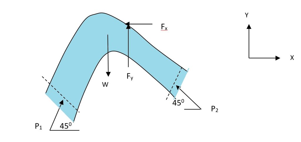
A 0.4m×0.3m, 90° vertical bend carries 0.6m³/s oil of specific gravity 0.8 with a pressure of 120 kPa at inlet to the bend. The volume of the bend is 0.1 m³. Find the magnitude and direction of the force on the bend. Neglect friction and assume both inlet and outlet sections to be at same horizontal level. Also assume that water enters the bend at 45° to the horizontal.

Given Data
Solution Approach
To determine the force on the bend, we’ll apply momentum equation and Bernoulli’s principle. First, we’ll calculate velocities at inlet and outlet, then find the pressure at the outlet using Bernoulli’s equation. Finally, we’ll apply momentum conservation in both X and Y directions to find the components of force on the bend.
Calculations
Preliminary Calculations
Step 1: Calculate the weight of oil in the bend:
Step 2: Calculate velocities at inlet and outlet:
Calculating Pressure at Outlet (P2)
Step 3: Apply Bernoulli’s equation between inlet and outlet (Z1 = Z2):
Determining Force Components
Step 4: Apply momentum equation in X-direction:
Step 5: Apply momentum equation in Y-direction:
Determining Resultant Force
Step 6: Calculate the resultant force and its direction:
Resultant force on the bend = 7526 N at an angle of 54° to the right and upward
Detailed Explanation
Working Principle of Force Analysis in Pipe Bends
When fluid flows through a bend in a pipe, it experiences a change in direction, which leads to a change in momentum. According to Newton’s Second Law, this change in momentum requires a force. The bend must exert this force on the fluid, and by Newton’s Third Law, the fluid exerts an equal and opposite force on the bend.
Pressure-Velocity Relationship
As the fluid flows from the larger section (inlet) to the smaller section (outlet), its velocity increases due to the continuity equation (A₁V₁ = A₂V₂). According to Bernoulli’s principle, this increase in velocity leads to a decrease in pressure at the outlet compared to the inlet, as we calculated (P₂ < P₁).
Components of Force on the Bend
The force on the bend consists of several components:
- Pressure forces acting on the inlet and outlet sections
- Momentum change of the fluid as it changes direction
- Weight of the fluid contained in the bend
Significance of Negative Fy
The negative value of Fy indicates that the force component in the Y-direction is acting downward. This is expected due to the high pressure forces acting on the bend and the change in momentum as the fluid changes direction.
Practical Applications
Understanding the forces on pipe bends is crucial in:
- Designing appropriate support structures for pipeline systems
- Ensuring structural integrity of piping under high-pressure conditions
- Preventing pipe failures and leakages in industrial applications
- Optimizing pipe layouts in chemical processing plants, water treatment facilities, and oil refineries
Analysis of Results
The calculated resultant force of 7526 N represents a significant load that must be accounted for in the design of the pipe support system. The direction of the force at 54° indicates that the support structure should be designed to counteract forces in both horizontal and vertical directions.
For engineers and students, understanding these principles is essential for designing safe and efficient fluid transport systems in various industrial applications, from water distribution networks to complex chemical processing plants.
