Problem Statement
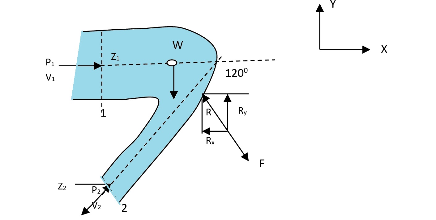
The diameter of a pipe bend is 30cm at inlet and 15cm at outlet, and the flow is turned through 120° in a vertical plane. The axis at inlet is horizontal and the center of the outlet section is 1.5m below the center of the inlet section. Total volume of water in the bend is 0.9m³. Neglecting friction, calculate the magnitude and direction of the force exerted on the bend by water flowing through it at 250lps and when the inlet pressure is 0.15N/mm².
Given Data
Solution Approach
To determine the force exerted on the pipe bend by flowing water, we’ll apply momentum principles and Bernoulli’s equation. We’ll first calculate key parameters including areas, velocities, and the outlet pressure, then resolve forces in x and y directions.
Calculations
Basic Parameters Calculation
Step 1: Calculate the cross-sectional areas at inlet and outlet.
Step 2: Calculate velocities at inlet and outlet using the continuity equation (Q = AV).
Step 3: Calculate the weight of water within the control volume.
Step 4: Apply Bernoulli’s equation to determine the outlet pressure.
With Z1 = 1.5 m, Z2 = 0 (taking outlet as reference), ρ = 1000 kg/m³, g = 9.81 m/s²:
Force Analysis
Step 5: Determine the angle for force resolution.
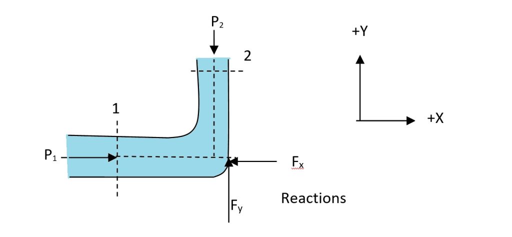
Step 6: Calculate the force in the X direction (horizontal).
Step 7: Calculate the force in the Y direction (vertical).
Step 8: Calculate the resultant force and its direction.
Resultant Force: 15481 N at 26.3° (to the right and downward)
Detailed Explanation
Principles Applied
This problem involves the application of two fundamental principles in fluid mechanics:
- Conservation of Energy (Bernoulli’s Equation): Used to determine the pressure at the outlet based on the given inlet conditions, velocities, and elevation changes.
- Conservation of Momentum: Applied to calculate the forces exerted by the flowing water on the pipe bend in both horizontal and vertical directions.
Significance of Each Force Component
The horizontal force component (Rx = 13882 N) is primarily due to:
- Pressure forces at inlet and outlet
- Change in momentum as water changes direction
The vertical force component (Ry = 6850 N) is influenced by:
- Weight of water within the bend
- Pressure force at the outlet in the vertical direction
- Momentum change in the vertical direction
Engineering Implications
The resultant force of 15481 N (approximately 1.5 tons) is significant and has several practical implications for the design and installation of the pipe system:
- Structural Support: The pipe bend must be adequately supported to withstand this force without deformation or failure.
- Anchoring: Proper anchoring systems must be designed to counteract this force, especially considering its direction at 26.3° from horizontal.
- Joint Design: Pipe joints and connections must be engineered to handle both the pressure and the mechanical forces.
- Foundation Requirements: The supporting structure or foundation must be capable of handling the load transmission from the pipe bend.
Effects of Flow Rate Variations
If the flow rate were to increase:
- Both velocities V1 and V2 would increase proportionally
- The momentum change would increase as the square of the velocity
- The resultant force would increase significantly
This highlights the importance of considering maximum flow conditions in the design of pipe bends, particularly in systems where flow rates may vary or where surge conditions might occur.
Practical Applications
Understanding the forces in pipe bends is crucial in many engineering applications:
- Municipal water distribution networks
- Industrial fluid transport systems
- Hydropower installations
- Irrigation systems
- Fire protection systems
In all these applications, proper calculation and accounting for the forces exerted on bends and other components is essential for safe, reliable, and efficient operation.