Problem Statement
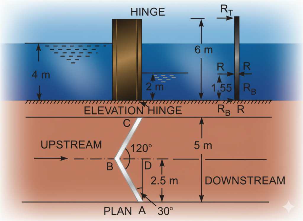
Each gate of a lock is 5 m high and is supported by two hinges placed on the top and bottom of the gate. When the gates are closed, they make an angle of 120°. The width of the lock is 4 m. If the depths of water on the two sides of the gates are 4 m and 3 m respectively, determine: (i) the magnitude of resultant pressure on each gate, and (ii) magnitude of the hinge reactions.
Given Data
- Gate height = 5 m
- Hinge locations: Top (5 m) and Bottom (0 m)
- Angle between gates = 120°
- Lock width = 4 m
- Upstream water depth, \( H_1 = 4 \, \text{m} \)
- Downstream water depth, \( H_2 = 3 \, \text{m} \)
Solution
1. Gate Geometry
First, calculate the angle \( \theta \) for one gate with respect to the lock's centerline and the width of one gate leaf (\(l\)).
2. Forces on a Single Gate
Upstream Force (\(F_1\)):
This force acts at \( H_1 / 3 = 4/3 \approx 1.333 \, \text{m} \) from the bottom.
Downstream Force (\(F_2\)):
This force acts at \( H_2 / 3 = 3/3 = 1.0 \, \text{m} \) from the bottom.
(i) Resultant Pressure (Force) on Each Gate (\(F_R\))
(ii) Magnitude of Hinge Reactions
First, find the location (\(x\)) of the resultant force \(F_R\) by taking moments about the bottom of the gate.
The total hinge reaction \(R\) is equal to the reaction between gates \(P\).
Now, take moments about the bottom hinge (\(R_B\)) to find the top hinge reaction (\(R_T\)). The distance between hinges is 5 m.
Finally, find the bottom hinge reaction \(R_B\).
(i) Resultant Pressure (Force): \( F_R \approx 79.24 \, \text{kN} \).
(ii) Top Hinge Reaction: \( R_T \approx 27.91 \, \text{kN} \).
(ii) Bottom Hinge Reaction: \( R_B \approx 51.33 \, \text{kN} \).
Explanation of Concepts
Forces on Lock Gates: The net force on a lock gate is the difference between the hydrostatic force from the higher upstream water level and the force from the lower downstream level. This net force acts perpendicular to the gate's surface.
Equilibrium of Gates: This net water force (\(F_R\)) is balanced by two other forces: a compressive reaction force (\(P\)) from the opposing gate where they meet, and a total reaction force from the hinges (\(R\)). For the standard miter gate design, the hinge reaction \(R\) is equal in magnitude to \(P\).
Hinge Force Distribution: The total hinge reaction (\(R\)) is distributed between the top and bottom hinges. To find the individual forces on each hinge, we use the principle of moments. By taking moments about one hinge, we can calculate the force on the other, ensuring the gate does not rotate.