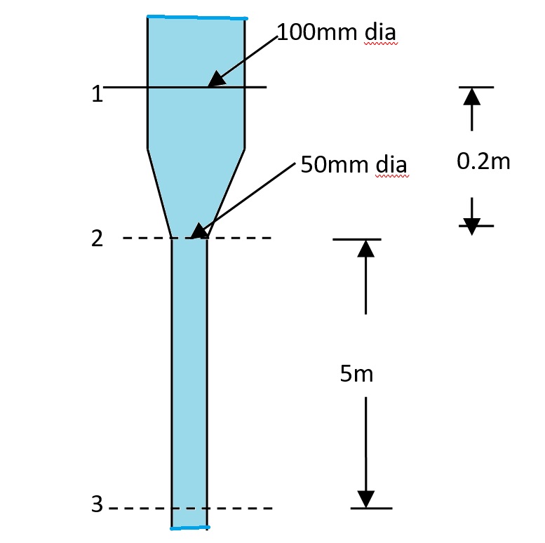
A 2.5m long pipeline tapers uniformly from 10cm diameter to 20cm diameter at its upper end. The pipe centerline slopes upwards at an angle of 300 to the horizontal and the flow direction is from smaller to bigger cross-section. If the pressure at lower and upper ends of the pipe are 2bar and 2.4bar respectively, determine the flow rate and the pressure at the mid-length of the pipeline. Assume no energy losses.
Tapered Pipeline Analysis Analysis of Tapered Pipeline with Upward Slope Problem Statement A 2.5m long pipeline tapers uniformly from 10cm […]