Table of Contents
TogglePlane Table Surveying is a method of surveying where field observations and plotting occur simultaneously. This technique allows for real-time representation of various features on the earth’s surface. To achieve accurate and precise results, the surveyor must possess not only technical skills but also a keen sense of artistry, as the ability to visually interpret and depict the landscape is crucial in this method.
Principle of Plane Table Survey
The principle of plane tabling is founded on the concept that the lines drawn on the plane table should be parallel to the corresponding lines connecting the actual points on the ground at each survey station. This principle can be more easily understood by considering the graphical reduction of a triangle to a given scale. First, the base of the triangle is plotted on the desired scale. Then, the angles at the base are determined directly by aligning the alidade at each endpoint. The point where the rays intersect marks the location of the triangle’s third vertex. In essence, plane tabling involves the graphical construction of straight lines, angles, and triangles to accurately represent the details of the surveyed area.
Instrument Used in Plane Table Survey
Planetabling requires a specific set of tools to ensure accurate surveying. The following instruments are crucial for this method:
- Plane table with supporting stand
- Alidade or sight rule for sighting and measuring
- Spirit level for ensuring proper alignment
- Magnetic compass for orientation
- Plumbing fork
- Suitable drawing paper
1. The Plane Table
The plane table is a wooden table mounted on a lightweight tripod, designed to rotate around its vertical axis and be clamped securely in any desired position. The table is leveled by adjusting the tripod legs. Typically, the table measures 750 mm × 600 mm, and the tripod legs are about 1200 mm long. The instrument is crafted from well-seasoned wood, with metal components such as the plate, bolts, nuts, and screws made of brass, and the leg shoes made of iron.

Qualities of a Good Plane Table
A good plane table should meet the following criteria:
- The table-top must be perfectly flat and free of knots.
- The butterfly nuts that clamp the legs to the clamping head should fit securely.
- The clamping assembly must fit properly with the plate at the bottom of the table.
- The annular ring should be securely fixed to the plane table.
- When properly clamped, the table-top should remain stable without any movement.
2. The Alidade
The alidade is a crucial instrument in plane table surveying, serving as a straight edge equipped with a sighting device to help align and measure angles. There are two main types of alidades commonly used:
Plain Alidade: A simple tool with a straight edge and basic sighting vanes, typically used for level terrain where elevation differences are minimal.
Telescopic Alidade: A more advanced version, featuring a small telescope mounted on the straight edge. This type is ideal for surveys where precision is essential, especially in areas with significant elevation changes.
(i). Plain Alidade
A plain alidade typically consists of a metal or wooden rule with two vanes at each end, which are hinged and can be folded onto the rule when not in use.(Refer to figure below)
- Sight Vane: One of the vanes, called the sight vane, has a narrow slit with three small holes—one at the top, one at the bottom, and one in the middle.
- Object Vane: The other vane, known as the object vane, is open and has a fine thread or thin wire stretched between its top and bottom.
When you look through the slit in the sight vane, you can line up your view with the object you’re measuring. This creates a line of sight that runs parallel to the ruler’s edge. You can rotate the alidade around the point on the map that represents your position, so the line of sight passes through the object you’re sighting.


To be effective, the ruling edge of the alidade (known as the fiducial edge) should be at least as long as the longest side of the plane table. The vanes must remain perpendicular to the table surface to ensure accurate sighting. The plain alidade is best suited for situations where the objects being surveyed are at similar elevations or have minimal variations in height. However, if the elevation difference exceeds what the line of sight can accommodate, the alidade can still be used by tightly stretching a thin thread between the tops of the sight and object vanes to maintain accuracy. (When elevation differences exceed the alidade’s line of sight capability, use a thin thread stretched between the tops of the sight and object vanes. Align the thread with the target object through the sight vane’s slit. This technique helps maintain accuracy despite height variations.)
(ii). Telescopic Alidade
A telescopic alidade is an alidade fitted with a telescope, making it ideal for taking inclined sights. The telescope enhances the range and accuracy of measurements. It includes a small telescope equipped with a level tube and a graduated scale mounted on a horizontal axis. This horizontal axis is supported by an A-frame, which is attached to a heavy metal ruler. The ruler has a working edge used for drawing lines.
With the telescopic alidade, you can measure angles of elevation or depression using the vertical circle. Additionally, the horizontal distance between the instrument station and a detail point can be determined by taking stadia readings on a leveling staff held at the point, applying tacheometric formulas. The difference in elevations can be calculated by multiplying the horizontal distance by the tangent of the angle of elevation or depression. Tacheometric tables can also be used to find the horizontal and vertical distances between stations.


3.Spirit Level
The spirit level is a small, essential tool in plane table surveying. It typically consists of a small metal tube containing a bubble of air. This tool may also come in a circular form, but regardless of its shape, it must have a flat base to rest securely on the table. The purpose of the spirit level is to ensure the plane table is perfectly level. The table is considered truly level when the bubble remains centered as you move the spirit level across different parts of the table.

4.The Magnetic Compass
The magnetic compass, often a box compass, features a magnetic needle pivoted at its center, allowing it to move freely. It is primarily used to orient the plane table to magnetic north. The edges of the compass are straight, and the bottom is perfectly flat to ensure stability when placed on the table.
To temporarily adjust for dip (the needle’s inclination), a small rider can be tied around the elevated end. It is crucial that the magnetic needle is sensitive and moves freely. If the compass needle doesn’t function properly due to a worn-out agate bearing, it should be replaced with a new one.
At the first plane table station, the longer edges of the compass are aligned parallel to the sides of the plane table. The table is then rotated until the needle points in the North-South (N-S) direction. A line drawn along the longer edge of the compass represents magnetic north. If ground control points are already plotted on the sheet, the table is oriented with respect to these points. The box compass is then rotated until its needle aligns with the N-S direction, and a line is drawn along the edge of the compass to mark the magnetic north.

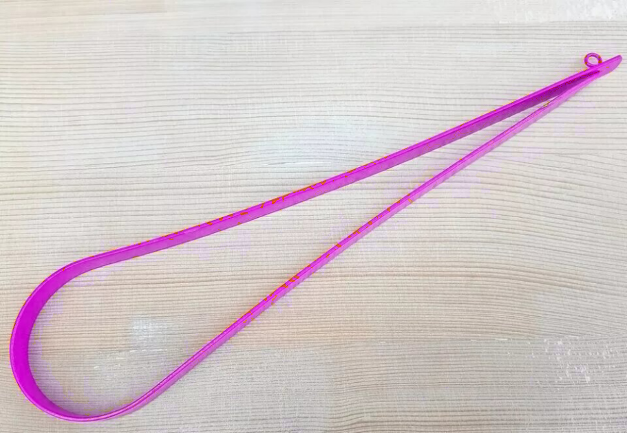
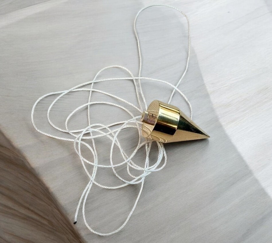
5.Plumbing Fork
The plumbing fork is a hairpin-shaped brass frame with two equal arms. One arm ends in a pointer, while the other has a plumb bob attached. This tool is crucial in large-scale surveys for accurately centering the plane table over the station location on the ground. It also helps in transferring the location of the instrument station from the sheet onto the ground.
To use the plumbing fork, place the upper arm on top of the plane table and the lower arm beneath it. The table is considered centered when the plumb bob hangs freely over the ground mark, ensuring accurate alignment. The pointed end of the fork indicates the precise location on the plane table.
In smaller-scale surveys, exact centering of the point is less critical. In such cases, the center of the table can be used as the approximate location of the ground station.
6.Drawing Paper
The drawing paper used for plane tabling should be of superior quality to withstand erasing and repeated handling. It should also be resistant to distortion caused by climatic changes, as fluctuations in humidity can alter the paper’s dimensions unevenly. To minimize the effects of shrinkage and expansion due to atmospheric humidity, the drawing paper is sometimes mounted on a zinc sheet, which helps maintain its stability during the survey.
Working Operations
The following three essential operations are carried out at each plane table station to ensure accurate and efficient surveying:
(i) Fixing the plane table on the tripod
(ii) Setting up the plane table
(iii) Sighting the ground stations and intersected points
(i) Fixing the plane table on the tripod
Begin by unfolding the leather strap of the tripod and spreading the legs evenly. Position the tripod so that its top is approximately 1.2 meters above ground level. Remove the bolt from the brass annular ring and place the plane table on top of the tripod, ensuring it fits securely with the clamping assembly. Finally, tighten the bolt with a washer to secure the table in place.
(ii) Setting up the plane table
The setting up operation consists of three crucial steps:
(a) Levelling the plane table
(b) Centering the plane table
(c) Orienting the plane table
(a). Levelling
The goal is to make the table top truly horizontal. For rough, small-scale work, levelling can be done by eye estimation, but for accurate, large-scale work, use a spirit level. This is particularly important in hilly terrain where control points vary in elevation, as incorrect levelling can significantly distort the location of points on the map.
Procedure:
- Step 1: Position the plane table at a convenient height (around 1.2 meters) by spreading the tripod legs to keep the table approximately level. Ensure the location of the station is roughly centered over its ground position.
- Step 2: Rotate the plane table until its longer edge is parallel to the line joining the shoes of any two tripod legs. Position the third leg so it points toward you and is placed between your legs.
- Step 3: Place the spirit level on the table parallel to its longer edge. Adjust the third leg left or right until the bubble is centered.
- Step 4: Rotate the spirit level 90° to check the other axis. Move the third leg forward or backward to center the bubble again.
- Step 5: Rotate the table 180° to verify that the bubble remains centered. Repeat the process if necessary to achieve accurate levelling.
(b).Centering
In this step, the plane table’s position on the drawing paper is aligned directly above the corresponding ground station.
- For rough and small-scale work: Exact centering isn’t crucial; the center of the table can simply be placed over the ground position.
Procedure:
- Step 1:Place one end of the U-fork on the plotted location on the paper, with the plumb bob hanging from the other end below the table.
- Step 2: Adjust the table’s position so that the plumb bob points directly to the ground station without disturbing the levelling.
- Step 3: Ensure the table is roughly oriented before final centering to avoid disturbing the setup during orientation.
(c). Orientation.
Orientation ensures the plane table is aligned correctly at each station so that the edges make a fixed angle with a fixed direction, known as the meridian. Proper orientation is crucial; if the table isn’t oriented correctly, the locations of detail points won’t accurately represent their relative positions.
Key Principle: The lines joining the locations of ground stations on the sheet must be parallel to their corresponding ground lines. This is achieved by rotating the table about its vertical axis.
Impact: Orientation may disturb centering, and vice versa. For accurate and large-scale work, it’s important to check centering before orientation and repeat both processes as needed to satisfy both conditions.
Methods of Orientation:
- Using a magnetic compass.
- Using a back ray.
Method 1: Orientation with a Magnetic Compass
When true north is unknown, magnetic north can serve as a reference meridian.
Starting Station: Set the table so that the entire area fits on it. Place a box magnetic compass on the table and align it so the needle rests in the N-S direction. Draw a pencil line along the longer edge of the compass to mark magnetic north.
Subsequent Stations: After leveling and centering the table, align the compass with the drawn magnetic north. Rotate the table until the needle points to N-S again, then clamp the table in place. The table is now correctly oriented to the magnetic meridian, provided there is no local attraction affecting the compass.
Method 2: Orientation with a Back Ray
This method involves using a ray drawn from the instrument station to the next forward station.
At the Current Station: Draw a ray from the plotted location of the instrument to the forward station. Mark the extremities of this ray on the alidade.
At the Forward Station: Place the alidade along the previously drawn ray. Rotate the table until the line of sight intersects with the previous station. This process is known as “setting by the back ray.”
Advantages: This method avoids issues with magnetic compasses and local magnetic attractions. Ensure that the same edge of the alidade is used for drawing lines, and verify that the back ray remains vertically above the ground position of the forward station.
(iii). Sighting the Ground Station
In this step, the plane table is centered and leveled precisely over the ground station.
Setup: Position the fiducial edge or working edge of the alidade on the plotted location of the instrument station.
Sighting: Look through the sight vane of the alidade and align it so that the station, the thread of the object vane, and the slit hole of the sight vane form a straight line.
Purpose: This operation is essential for accurately plotting all stations or details on the plane table, whether their locations are known or being surveyed.