Table of Contents
ToggleAdjustment of a Level
Adjustment of a Level refers to the process of aligning and calibrating a leveling instrument to ensure accurate readings. A level instrument requires two primary types of adjustments to ensure accurate functioning:
- Temporary Adjustments: These are made each time the level is set up for use.
- Permanent Adjustments: These adjustments are made to correct any mechanical misalignments or calibration issues in the instrument and are typically performed by a professional.
Temporary Adjustments of a Level
Temporary adjustments refer to those that are performed for every individual setup of the leveling instrument. These are critical for ensuring accurate and precise measurements on-site and consist of the following three steps:
- Setting up the Level
- Levelling up
- Elimination of Parallax
1. Setting up the Level
Setting up the level involves fixing the instrument securely on the tripod and making an approximate level adjustment using the tripod legs. Here’s a step-by-step breakdown of the process:
- Begin by releasing the clamp that secures the instrument.
- Hold the level firmly with your right hand, and with your left hand, rotate the levelling head to attach it to the tripod.
- Adjust the legs of the tripod to ensure that the instrument is at a comfortable height for the user and that the base of the level (tribrach) is approximately horizontal.
- Modern leveling instruments are equipped with a small circular bubble located on the tribrach, which helps in achieving an approximate level. Ensure the bubble is close to the center to proceed with more precise adjustments in the next step.
In more advanced levels, automatic compensators may help in minimizing minor errors caused by slight inclinations, allowing for more accurate readings during use.
2. Levelling up
Once the level has been set up, the next step is precise levelling, which is essential to ensure that the instrument’s vertical axis is perfectly vertical. This is achieved using foot screws and plate levels. Depending on the number of foot screws on the levelling head, there are two main methods for accurate levelling:
Method 1: Levelling with a Three-Screw Head

This method involves the following steps:
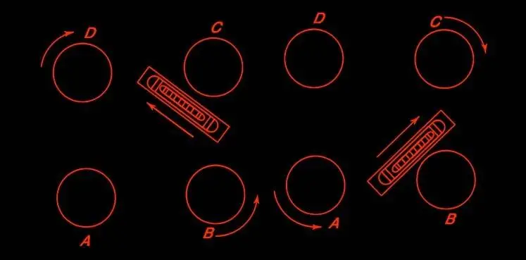
Initial Alignment: Loosen the clamp and rotate the instrument so that the longitudinal axis of the plate level aligns with the line joining two of the levelling screws (A and B).
Adjusting the Bubble: Using your thumb and index finger, turn the two screws (A and B) simultaneously in opposite directions. Move the thumbs toward or away from each other until the bubble in the plate level is centered. The bubble will move in the same direction as the left thumb.
Rotate the Plate: Turn the upper plate of the instrument by 90° so that the axis of the plate level aligns with the line joining the third screw (C) and the midpoint of the first two screws (A and B).
Adjust the Third Screw: Hold the third screw (C) with your right hand and turn it until the bubble is centered again.
Repeat Steps: Rotate the plate back by 90° to its original position and repeat step 2 to ensure the bubble is still centered.
Further Rotation: Rotate the upper plate through another 90° and repeat the adjustment using the third screw (C) as in step 4.
Verify Accuracy: Continue alternating between adjusting the two screws (A and B) and the third screw (C) until the bubble stays centered in both positions.
Final Check: Rotate the instrument 180°. If the bubble remains centered, the instrument is properly adjusted, and the vertical axis is truly vertical. If not, permanent adjustments are required.
Note: Always rotate the instrument in the same quarter of the circle during adjustments, avoiding swinging through the remaining three-quarters of the circle. This ensures consistent results.
Method 2: Levelling with a Four-Screw Head
When levelling an instrument with a four-screw head, the process is slightly different due to the additional screw. The following steps outline the procedure:
Initial Alignment: Loosen the clamp and rotate the upper plate until the longitudinal axis of the plate level is approximately parallel to the line joining two diagonally opposite foot screws, such as screws B and D.
Center the Bubble: Adjust the screws in the same manner as described in the three-screw method, turning them simultaneously until the bubble in the plate level is centered.
Rotate the Plate: Turn the upper plate 90° so that the axis of the plate level is now parallel to the other two diagonally opposite screws, A and C .
Center the Bubble Again: Adjust the screws A and C as you did with the first pair, ensuring the bubble is centered.
Repeat the Process: Continue alternating between adjusting screws B-D and A-C until the bubble remains central in both positions.
Final Check: Turn the instrument 180° and check that the bubble remains centered, as with the three-screw method. If it remains central, the instrument’s vertical axis is now truly vertical. If not, permanent adjustment may be necessary.
Notes while Levelling with a Four-Screw Head:
- Two Plate Levels: If the instrument is equipped with two plate levels set at right angles, step 4 is unnecessary, as the instrument will be level in all directions after the initial adjustment.
- Tripod Levelling: Ensure the tribrach is approximately levelled during setup to prevent jamming of the screws, which can occur if the instrument is tilted too far.
- Firm Screw Positioning: The foot screws should rest firmly on the lower parallel plate, without rocking.
- Avoid Over-tightening: Never apply excessive force to the screws when levelling, as this can damage the instrument.
- Mid-Range Positioning: The foot screws should ideally be positioned in the middle of their range to allow for finer adjustments in both directions.
3. Elimination of Parallax
Parallax occurs when the image formed by the objective lens does not lie on the same plane as the crosshairs, causing the image to shift when the observer’s eye moves. To ensure accurate sighting and eliminate parallax, two key adjustments must be made: focusing the eyepiece and focusing the objective lens.
1. Focusing the Eyepiece
To obtain a clear view of the crosshairs, follow these steps:
- (i) Point the telescope either towards a bright sky or place a white sheet of paper in front of the objective lens.
- (ii) Adjust the eyepiece by moving it in or out until the crosshairs appear sharp and clear.
Some instruments come with numbered and graduated eyepieces for easier reference. Once properly focused, you can note the position of the eyepiece to save time for future observations.
2. Focusing the Objective
To ensure the image is sharply aligned with the crosshairs, follow these steps:
- (i) Aim the telescope at the levelling staff.
- (ii) Adjust the focus screw until the image is crisp and clear.
- (iii) Ensure that the image aligns with the plane of the crosshairs to prevent any residual parallax from affecting measurements.
By completing these steps, parallax is effectively eliminated, ensuring the accuracy of readings taken through the level.
Temporary Adjustments of a Tilting Level
The temporary adjustments for a tilting level are a bit more intricate compared to standard levels due to the presence of a micrometer screw. The following steps guide the process:
Setting up the Level: Position the instrument securely on stable ground using the tripod, ensuring the base is firm and steady.
Preliminary Levelling with the Circular Bubble: Adjust the legs of the tripod to bring the circular bubble into its central position. This ensures the vertical axis of the instrument is approximately vertical.
Zeroing the Micrometer Screw: Adjust the micrometer (or tilting) screw so that the reading is set to zero. At this point, the two halves of the main bubble should appear within the prism field.
Directing and Focusing the Telescope: Aim the telescope toward the levelling staff and use the focusing screw to achieve a clear, sharp image of the staff.
Fine Levelling with the Micrometer Screw: Slowly turn the micrometer screw until the end of the main bubble coincides precisely with its index line. For modern tilting levels, where the bubble is viewed through a prism, the two halves of the bubble will appear aligned when properly centered, forming a complete bubble.
Permanent Adjustments of a Level
Permanent adjustments are made to ensure that all essential parts of the instrument are correctly aligned relative to one another. These adjustments are crucial for maintaining accuracy and reliability during surveying tasks. Ideally, permanent adjustments should be as precise as possible to prevent measurement errors.
For a level, perfect permanent adjustment is not always necessary if care is taken to balance the backsight and foresight distances during measurements. In doing so, any minor errors due to imperfect adjustments can be canceled out. However, it is still important for a surveyor to understand how to test and correct these adjustments to ensure optimal instrument performance.
Principle of Reversal:
The testing and correction of a level’s permanent adjustments are based on the principle of reversal. This principle states that if an error exists in a certain component of the instrument, it will become more pronounced when that part is reversed, i.e., rotated by 180°. This concept is key to identifying and correcting misalignments. (When the instrument is rotated 180°, any errors that were present become more noticeable, allowing the surveyor to identify and correct them. This technique is used for ensuring the accuracy of permanent adjustments like the line of collimation and bubble tube alignment.)
Fundamental Lines of a Level:
A level instrument has several fundamental lines that must maintain fixed relationships with one another to function correctly. These lines are:
- The Axis of the Bubble Tube: The straight line passing through the center of the bubble in the tube.
- The Vertical Axis: The axis around which the instrument is rotated horizontally.
- The Axis of the Telescope: The axis along the length of the telescope through which the sighting occurs.
- The Line of Collimation: The straight line passing through the center of the crosshairs in the eyepiece and the optical center of the objective lens.
Over time, these relationships may be disturbed due to rough handling in the field, requiring periodic adjustment. The desired relationships between the fundamental lines are as follows:
- The vertical axis of the instrument should be perpendicular to the axis of the plate bubble tube. This ensures that the instrument is level when the bubble is centered.
- The line of collimation should be perpendicular to the vertical axis. This ensures that the telescope maintains a horizontal sightline when rotated.
- The axis of the telescope should coincide with the line of collimation. This guarantees that the center of the crosshairs aligns with the true sighting direction.