Table of Contents
ToggleReverse Curve/Serpentine Curve/S-Curve
A reverse curve is formed by two circular arcs, either of equal or differing radii, with their centers located on opposite sides of a shared tangent at the point where the curvature changes direction.
The defining characteristic of a reverse curve is the positioning of the arc centers. Each circular segment has its center located on opposite sides of the shared tangent line that passes through their junction. This arrangement allows for a fluid change in direction without the need for a straight section between curves.
In Figure below, the curve T₁TT₂ illustrates a reverse curve, consisting of two arcs, T₁TV and T₂TU, with radii R₁ and R₂, respectively. These arcs connect two straight lines, T₁U and T₂V. Reverse curves are frequently found in railway yards but are generally unsuitable for modern highways due to their shape. They are also commonly referred to as serpentine or S-curves because of their distinctive form.

Disadvantages of a Reverse Curve
For high-speed vehicles on highways and main railway lines, the use of reverse curves is discouraged due to the following reasons:
- Abrupt Superelevation Transitions:
- In a reverse curve, vehicles must quickly transition from one banked position to the opposite.
- This rapid shift in superelevation can induce instability, especially at high speeds.
- The lateral forces experienced during this transition can be unpredictable and difficult for both drivers and vehicle suspension systems to manage.
- Lack of Superelevation at Reverse Points(Superelevation Void at Inflection Point):
- At the precise point where the curve reverses direction (the inflection point), there is a moment of zero superelevation.
- This brief flat spot creates a potentially dangerous situation where centrifugal forces are not adequately counteracted.
- For rail vehicles, this can lead to increased wheel wear and potential derailment risks.
- Steering Complexity and Safety Risks:
- On highways, navigating a reverse curve requires quick, precise steering adjustments.
- The rapid directional change demands heightened driver attention and skill.
- Less experienced drivers or those in adverse conditions (e.g., wet roads, low visibility) face increased risks of overcorrection or loss of control.(Overcorrection in reverse curves refers to the dangerous tendency of drivers to excessively steer when navigating the rapid directional changes, potentially leading to loss of vehicle control.)
- Tall vehicles or those with high centers of gravity are particularly susceptible to rollover in these situations.
- Passenger Comfort and Safety:
- The sudden change in direction subjects passengers to abrupt lateral forces.
- This can cause discomfort, motion sickness, and in extreme cases, injuries if passengers are unprepared for the movement.
- In public transportation, such as trains or buses, this discomfort can be particularly pronounced for standing passengers.
To mitigate these risks, it is recommended to introduce a short, straight segment between the two circular arcs of a reverse curve. This straight portion allows for:
- Gradual transition of superelevation
- A brief “rest” for drivers between steering maneuvers
- Improved sight lines and reaction time for upcoming directional changes
- Enhanced overall comfort and safety for all users of the transportation system
Whenever possible, designers opt to eliminate reverse curves entirely on high-speed routes.
Elements of a Reverse Curve
The main components of a reverse curve include the following:
- Radii of Curvature:
- R1: Radius of the first circular arc
- R2: Radius of the second circular arc These radii determine the sharpness of each curve segment.
- Total Deflection Angle (∆): This represents the overall change in direction between the entry and exit straights. It’s a critical factor in determining the curve’s impact on vehicle dynamics.
- Deflection Angles of the Common Tangent:
- ∆1: Deflection angle for the first curve
- ∆2: Deflection angle for the second curve These angles measure how much each curve segment deviates from the common tangent line.
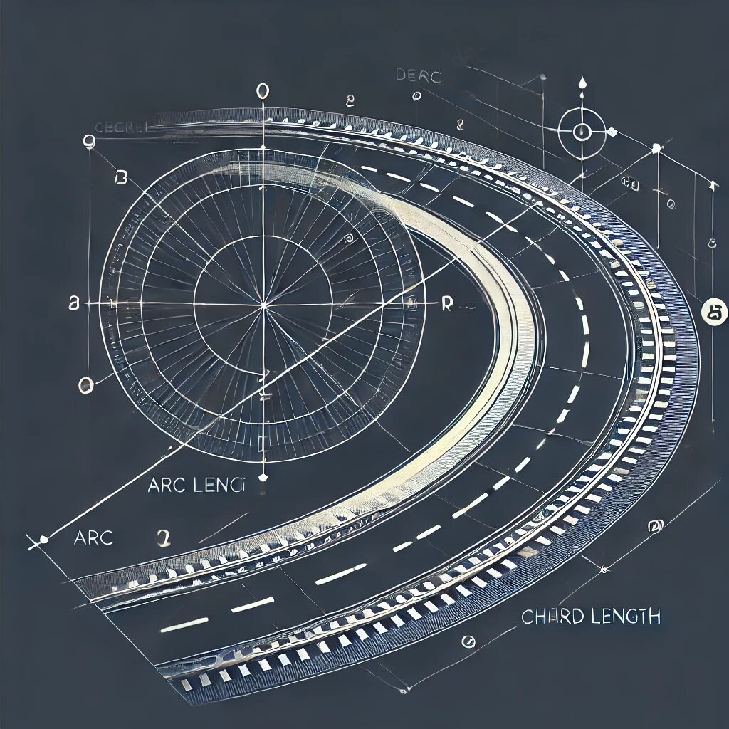
- Angles Between Straights and Chord Line:
- δ1: Angle between the entry straight and the chord line
- δ2: Angle between the exit straight and the chord line The chord line here refers to the straight line connecting the points of curve entry and exit.

Design Constraints and Assumptions:
In practical reverse curve design, certain assumptions are typically made to simplify calculations and ensure geometric consistency:
- Equal Radii Assumption: Often, engineers set R1 = R2 to create a symmetrical curve profile. This simplifies calculations and can provide a more aesthetically pleasing and predictable curve.
- Balanced Deflection Angles: Setting ∆1 = ∆2 ensures that both curve segments contribute equally to the overall direction change. This can help in maintaining consistent vehicle dynamics throughout the curve.
- Known Chord Length: Specifying the length of the line joining the tangent points (chord length) provides a crucial dimensional constraint. This helps in fitting the reverse curve into the available space and coordinates with other design elements.
These assumptions allow to solve for the remaining variables and fully define the reverse curve geometry. However, it’s important to note that in real-world applications, these conditions might be adjusted based on specific site constraints, design speeds, or other factors.