

Pipe Branch Force Calculation
Problem Statement
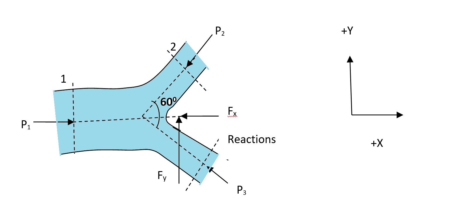
A main pipe of diameter 500mm branches in two pipes of diameter 300mm each in the horizontal plane. Angle between the branches is 60°, which is symmetrical with respect to the main pipe. Flow discharge through the main pipe is 1.0 m³/s, which is equally divided into the branch pipes. If the pressure intensity at the main pipe is 400 kPa, find the magnitude and direction of resultant force in the bend. Assume no loss of energy due to branch junction and in pipe sections.
Given Data
Solution Approach
To find the resultant force exerted on the pipe branch, we need to:
- Calculate the cross-sectional areas and velocities in all pipes
- Determine the pressures at outlet sections using Bernoulli’s equation
- Apply the momentum equation to determine the forces in both X and Y directions
- Calculate the resultant force and its direction
Preliminary Calculations
Step 1: Calculate the cross-sectional areas:
Step 2: Calculate the velocities:
Pressure Determination
Step 1: Apply Bernoulli’s equation between sections 1 and 2:
Since the pipes are in a horizontal plane, Z₁ = Z₂:
Step 2: Similarly, apply Bernoulli’s equation between sections 1 and 3:
Since conditions for pipe 3 are identical to pipe 2:
Force in X-Direction
Step 1: Apply the momentum equation in the X-direction:
Step 2: At section 1, the velocity is entirely in the X-direction (V₁x = V₁). At sections 2 and 3, the X-components of velocity are (V₂x = V₂Cosθ and V₃x = V₃Cosθ).
Step 3: Solve for Fx:
Force in Y-Direction
Step 1: Apply the momentum equation in the Y-direction:
Step 2: At section 1, there is no Y-component of velocity (V₁y = 0). At section 2, the Y-component is positive (V₂y = V₂Sinθ). At section 3, the Y-component is negative (V₃y = -V₃Sinθ) due to the symmetry.
Step 3: Solve for Fy:
The Y-component of force is zero due to the symmetrical arrangement of the branch pipes.
Resultant Force Calculation
Step 1: Calculate the magnitude of the resultant force:
Step 2: Calculate the direction of the resultant force:
Summary
-
The fluid velocities in the pipes were calculated:
- Main pipe velocity (V₁) = 5.09 m/s
- Branch pipe velocities (V₂ = V₃) = 7.07 m/s
-
The pressures at branch outlets were determined using Bernoulli’s equation:
- P₂ = P₃ = 387,962 Pa ≈ 388 kPa
-
The force components were calculated using the momentum equation:
- X-direction force: Fx = 30,506 N
- Y-direction force: Fy = 0 N (due to symmetry)
-
The resultant force on the pipe branch:
- Magnitude: 30.5 kN
- Direction: 0° (along the main pipe axis)
This problem demonstrates the application of the momentum equation in fluid mechanics to determine forces on pipe branches. The force is significant due to both the pressure forces and the momentum change of the fluid as it divides and changes direction. The symmetrical arrangement of the branch pipes results in a net force that acts only in the axial direction of the main pipe, with no lateral component.


